
There's nothing like getting your hands on a knob and giving it a good wiggle. Stop laughing at the back, please, I'm being serious.
Any composer who's programmed music using a DAW knows that to get realistic-sounding sounds from virtual instruments you need to adjust them as you play them. A piano keyboard is great for starting and stopping notes, even being aware of how hard you press the keys, but they generally don't control what happens to the note while it is being played. For that, you need a MIDI controller.
The use of MIDI controllers, as they're called, is expertly explained in this video from Christian Henson at The Crow Hill Company. Essentially, a controller, usually a knob or a fader - something you can physically interact with, sends non-musical data to the computer which is used by your virtual instrument to somehow change the sound it is creating. The flexibility this gives is endless and controllers exist in all shapes and sizes.
MIDI controllers are also catnip to gear freaks. Look in the comments on just about any YouTube video about using orchestral virtual instruments and people will be asking what controller they saw on screen.
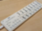
There are loads of MIDI controllers on the market. One of the cheapest is the Korg nanoKONTROL2, a handy little device that has knobs, buttons and faders. It's great, I use one.
But, I don't have 8 fingers in my left hand, I don't really use the knobs or buttons and, if I'm being critical, the faders are a bit lacking in travel for my liking. So it's both too big and too small for my ideal controller. What I really want is something with just a few, longer faders.
Of course, these are available. Products like the Monogram CC, the FVDE, the Nuances, the Dark Fader, the Faderbox, the Conductor, the Sparrow and many more are all on sale. But they're all either really expensive, not made in the UK (expensive to import) or made by a guy in a garage who only makes one a month so are perpetually out of stock. I've looked, longingly, at them all!
So I thought: it can't be that hard to make my own, can it?
..Hey presto!
Let's look at how this went together.
Component Selection
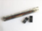
The most important part of the controller is the faders, it's what we're all here for. A fader is simply a potentiometer (variable resistor) laid out in a line with a movable wiper. These are commonly available, though longer ones less so, and I found Bourns 100mm 'audio quality' faders at CPC. I don't need audio quality but it's probably nice to have, hopefully it means they're really well made.
I also picked up some fader caps from eBay. There are loads to choose from.
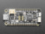
Then I needed something to convert the variable resistance from the fader into MIDI messages the DAW can decode. This is really easy with Arduino-like electronics boards because other people have gone to the trouble of writing MIDI implementations for them already. All this stuff is just ready to be wired up. I selected the Adafruit Feather RP2040. This little board has, amongst many other things, four analogue-to-digital converters (ADCs) well-suited to reading the varying voltage from the pots, doing some number processing and sending the resulting value out as MIDI. Four ADCs means four faders - perfect for me.
The Circuit
The pots have their two ends connected to ground (0V) and the supply voltage (3.3V for this board). The wiper moves up and down the resistor track forming a simple voltage divider: The voltage present on the input pin to the Feather's ADC varies from 0V to 3.3V, and the ADC converts this to a digital number we can use in our software.

R1-R4: 10k linear potentiometer
S1: Small switch/jumper to put the board into 'debug' mode
CircuitPython
Arduino boards are generally programmed in C, but Adafruit has developed CircuitPython (based on MicroPython) which is much more easy to use. From their website: CircuitPython is a programming language designed to simplify experimenting and learning to program on low-cost microcontroller boards.
With CircuitPython, the microcontroller board shows up in your PC as a USB disk drive. You write your Python in a basic text file and simply copy the file to the disk. The micro re-runs the code whenever it sees the file has changed. No needing a special editor, or having to compile code before uploading with a special programmer. It is mind-bendingly easy (and a really nice idea, well done Adafruit and MicroPython).
The Code
The full code is on GitHub but here is an explanation of the main parts. I have to thank the Grand Central USB MIDI Controller project, from which I took the basic set up. All code is written in a single file called code.py
Setup
We start by setting up our project, including the various libraries required for the ADCs and MIDI messaging.
import board
import time
import usb_midi
from simpleio import map_range
from analogio import AnalogIn
from digitalio import DigitalInOut, Direction
from adafruit_midi.control_change import ControlChange
We set up a MIDI interface, pick the pin to which a little red activity LED is connected and initialise some variables we'll use later. A single MIDI connection has 16 channels but we'll just send messages on channel 1.
MIDI_USB_channel = 1

midi_usb = adafruit_midi.MIDI(
    midi_out=usb_midi.ports[1], out_channel=MIDI_USB_channel - 1
)

led = DigitalInOut(board.LED)
led.direction = Direction.OUTPUT

knob_count = 4  	# Set the total number of potentiometers used
num_samples = 5 	# How many samples to average over
hyst_window = 300	# Hysteresis window
For ease of looping we'll create an array holding the four ADC pins. We use the handy getattr comand to perform lookups against our board (CircuitPython has standard helper libraries for this sort of thing.)
knob = []
for k in range(knob_count):
    knobs = AnalogIn(
        getattr(board, "A{}".format(k))
    )  # get pin # attribute, use string formatting
    knob.append(knobs)
We set up which MIDI controller number we want each fader to map to. Commercial controllers have ways to set this, sometimes using a menu, sometimes allowing programming commands from the PC. As this device is just for me I am not implementing such ease of use; I pick some controller numbers and code them in. If I want to change them later I'll need to update the code.
There are standard controller numbers for some functions. The two most commonly used are 1 (the modulation wheel) and 11 (expression, or volume). Most virtual instruments use at least one of these for their primary "sound changing" control and allow custom mapping of any other controllers to further parameters they may have. I picked 12 and 13 arbitrarily.
cc_number = [
    11,  # knob 1, expression
    1,   # knob 2, mod wheel
    12,  # knob 3, effect controller 1
    13,  # knob 4, effect controller 2
]
Next we initialise some data stores. These hold some constants we'll use to control loops and other range conversions and give us somewhere to hold values read in from the ADCs for processing and comparison.
# CC range list defines the characteristics of the potentiometers
#  This list contains the input object, minimum value, and maximum value for each knob.
#   example ranges:
#   0 min, 127 max: full range control voltage
cc_range = [
    (0, 127),  # knob 0
    (0, 127),  # knob 1
    (0, 127),  # knob 2
    (0, 127),  # knob 3
]

# Initialize cc_value list with current sample placeholders - this is a 2D array
cc_value = []
for i in range(knob_count):
    col = []
    for j in range(num_samples):
        col.append(0)
    cc_value.append(col)

# The value that last exceeded the hysteresis window
last_cc_value = []
for _ in range(knob_count):
    last_cc_value.append(0)

# The value we last sent out as MIDI
last_midi_value = []
for _ in range(knob_count):
    last_midi_value.append(-1)

sample_counter = 0
cts = False
The Main Loop
The microcontroller program simply runs in an infinite loop, reading values from the four ADCs, doing some data cleaning and comparison, and transmitting MIDI messages if necessary. It is essentially:
while True:
    # Loop through all knobs
    for aknob in range(knob_count):
		# Sample the fader
		# Send MIDI
    time.sleep(0.01)
Sampling the value from the ADC is just a case of reading it. The variable aknob tells us which of the four ADCs we're working on. We need to smooth the data out a bit (the ADC is quite noisy; whole books have been written on the interesting challenges posed at the interface between noisy wibbly analogue voltages and clean digital numbers) so we actually read five samples and take their average. This smooths out spikes. sample_counter points to the sample number (from 0 to 4) that we're currently reading, it is incremented once every time we go round our main loop and reset when it reaches 4.
# Sample the fader
cc_value[aknob][sample_counter] = knob[aknob].value

# Average the sample
averaged_sample = 0
for j in range(num_samples):
	averaged_sample += cc_value[aknob][j]
averaged_sample = averaged_sample / num_samples
Now we do something a little clever: Digital has a hard time representing analogue in the case that the voltage coming into the ADC happens to fall exactly on the boundary between two integers. You tend to get the converted digital value flipping backwards and forwards between the two values; The digital representation of the analogue value is both numbers and yet neither number at the same time. The sample averaging smoothing we're doing helps (to a point) but we can still get an oscillating digital value at the end.
To avoid sending MIDI messages continually flipping between two values, we apply some hysteresis. This means the sample has to move a certain amount away from where it last was before we take any notice.
To work out the hysteresis window we need to figure out the amount of "wiggle" we want to permit on the sampled value before we determine it to have really changed. Too little window and we'll end up with potentially 'false' changes detected. Too large and we'll have an insensitive fader. Experimentally I found that using a hysteresis value of 300 gave a good compromise between noise immunity and fader sensitivity.
The hysteresis window is applied (the variable cts inhibits us from sending MIDI messages is the sample buffer is still filling up):
if cts and abs(averaged_sample - last_cc_value[aknob]) > hyst_window:
	last_cc_value[aknob] = averaged_sample
If the sample value has breached the hysteresis window, it's time to send the new value as a MIDI message.. almost.
In practice, because MIDI data resolution (7-bit) is much lower than the resolution we get from the ADC (12-bit), it's possible that a sample value genuinely exceeds the hysteresis window but still converts to the same MIDI value. Increasing the hysteresis window to stop this would render the fader insensitive to small movements. So I bodged in one final check where I convert the value to MIDI and check it isn't the same as what we last sent.
map_range converts a number from one range to another. By using slightly off-end-endstop values for min (300) and max (65000), I give the faders a little bit of resting room at the very ends of their travel. This makes them easier to use because the min or max position is a fairly common resting place for a MIDI controller and I want to allow a little bit of finger wobble at these extents.
I also switch on the activity LED to show the board is transmitting something.
midival = int(map_range(last_cc_value[aknob], 300, 65000, cc_range[aknob][0], cc_range[aknob][1]))
if last_midi_value[aknob] != midival:
	last_midi_value[aknob] = midival
	led.value = True
	midi_usb.send(ControlChange(cc_number[aknob], midival))
Finally at the end of the loop we do a bit of sample_counter incrementing, wait a bit, and switch the LED off again:
sample_counter += 1
if sample_counter >= num_samples:
	sample_counter = 0

# stop us sending values until the sample averaging buffer is full
if not cts:
	cts = True

time.sleep(0.01)
led.value = False
CircuitPython Customisation
To make developing gadgets as easy as possible, a CircuitPython microcontroller board presents itself to the PC as various devices:
A MIDI device
A HID (keyboard and mouse) device
A USB disk (for code copying)
A serial port (for debugging)
For my project I never need the HID device, and the USB disk and debugging serial port are only useful during development or upgrades.
Through the use of some commands in a special bootup code file (boot.py) I can command CircuitPython to hide interfaces I don't want. Using a jumper connected to a spare digital input pin, I can switch the board into "debug mode" (programming interfaces available) or "normal mode" (things hidden).
import storage, usb_cdc, usb_hid
import board
from digitalio import DigitalInOut, Pull

# We never want to present as a HID
usb_hid.disable()

# This is a jumper that should be closed to ground for "debug mode"
button = DigitalInOut(board.D24)
button.pull = Pull.UP

# If high, jumper is OPEN (not debug), so disable the USB drive and the COM port
if button.value:
    storage.disable_usb_drive()
    usb_cdc.disable()

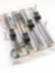
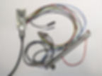
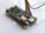
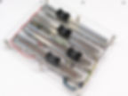
Prototype
Note the croc-clip cable temporarily grounding the unused ADC inputs.
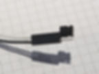
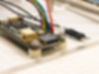
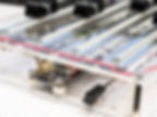
Debug switch
I don't expect to regularly need the device in "debug" mode, so I used a 0.1" header connector with a jumper instead of a switch. This photo shows the jumper in "open" mode for "normal" operation of the device.
Panel Mount
I considered a 3D printed enclosure but past experience has always disappointed, also it ends up quite expensive because you need an awful lot of filament to print a box strong enough at the sizes concerned here. Manually cutting slots out of a plastic box would look utterly awful (believe me; I've been there) so that's out of the question.
Instead I opted to use a laser-cut acrylic panel. I designed the layout (super simple) in CAD and sent it to a guy I found through Etsy - Welsh Laser Creations - for cutting. There is a top plate and a bottom plate. The latter has holes to secure the Feather board. The two plates will be fastened together by spacers; there won't be sides to this project (it's just for me, after all). Clear arylic should look pretty cool, too.

The boards took a week to arrive, and look waaaaay smart!
Final Asssembly
With all the holes pre-drilled in exactly the right places, assembly was reasonably quick. I also got all the holes countersunk so the screws are flush with the surface for maximum neatness.
The PCB fitted to the board with M2.5 screws. Due to the solder connections on the underside of the PCB, I needed small spacers to lift it away from the enclosure panel slightly.
I glued the debug header on with superglue.
The faders screwed to the underside of the top panel and were soldered once attached. This meant I could optimise the lengths of the wires to keep things neat.. ish. My soldering isn't brilliant, these days I'm a bit out of practice.
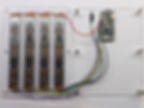
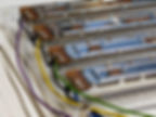
I put a bit of wrapping around the wires to keep them neat. Then I used 20mm nickel-plated spacers secured with M3 screws to attach the top board to the bottom board and finally stuck on some little plastic feet so it grips the desk.

The result:
The board ends up at 120mm wide by 150mm long. It stands 30mm off the desk not including the fader caps. It weighs about 250g, which, given its size, makes it feel reassuringly 'quality'.
The USB-C port just pokes out the end of the device, next to the debug header.
Obviously, this device could never be sold, you can reach your fingers in and scratch them on pointy metal connectors, or prod the contacts on the circuit board! It's all low voltage (5V from the USB port) so is, of course, totally safe for my use, and I like the open/engineering aesthetic. Also, this sort of assembly was much easier and cheaper than a full enclosure.
MIDI on the PC
The CircuitPython device appears with two MIDI ports. They're identically named but I guess one's input and one output. It isn't simple to change the naming; the CircuitPython libraries don't allow changing of the device names and you quickly get into fun with recompiling libraries, and USB device IDs and stuff. It's a shame, it would be cool to be able to name the MIDI ports, but that's beyond the hobbyist arena to which CircuitPython is targeted and I don't want it enough to deeply dive into this.

There are various programs that can decode and display incoming MIDI data. For this project I really didn't need much analysis, only something to display the data. MIDI-OX looks really fully-featured and did what I needed with ease - it's also ancient, written for Windows 95! But then MIDI hasn't changed for decades, either.

Debugging CircuitPython
CircuitPython has a simple debugging interface. Connect to the COM port that the board presents to the PC, and use print commands in the Python. The messages appear incoming from the COM port.
print("---Shizuka v1.0: MIDI Fader Controller---")
print(f"   USB MIDI channel: {MIDI_USB_channel}")

for i in range(knob_count):
    print(f"   MIDI Fader {i + 1}: CC{cc_number[i]}")
Cost of Components
While the cost of the commercial versions of these sorts of fader controllers was a major factor in my decision to build my own, obviously I like project electronics like this and it was a lot of fun playing with CircuitPython, MIDI, and stuff. But let's do a quick summary of the costs. Prices are rounded.
4 x slide potentiometers: £21
4 x fader caps: £2
Adafruit Feather RP2040 microcontroller: £12
Laser-cut acrylic panels: £10
Wires, screws & spacers: £5 (guess; I have this stuff in abundance so it wasn't purchased specially for this project)
The total for the components came to about £50. That's a significant saving over the commercial versions of this. BUT, obviously my version of this device isn't suitable for others to use on account of it being totally open to prying fingers at the sides. My time was free, and I haven't had to go through any product testing, don't have a support department and haven't designed in any notion of robustness that you'd need if you were selling this to others.. in short it's a totally unfair comparison to make.
Final Thoughts
This was a fun project, I saved a pile of money compared to buying this kind of device from someone else, and above all I've got a really nice fader controller to use in my music-making.